
Maintenance
Read and understand the Safety section before proceeding.
To prevent the engine from unintended starting, remove the spark caps from the spark plugs before performing any service procedure.
Proper maintenance can prolong the life of unit. The Maintenance Schedule shows the recommended service schedule. Maintenance will decrease the machine downtime and prevent any major and expensive repairs. This section covers suggested maintenance procedures that should be performed on a regular basis.
The service intervals should be considered the minimum recommended maintenance. More frequent service may be required due to working conditions (heavy loads, high ambient temperatures, dusty conditions, or airborne debris). Never operate the machine when any warning lights, or signals are on.
Contact an authorized engine manufacturer's service center for engine service.
Emission Control System
This equipment and/or its engine may include exhaust and evaporative emissions control system components required to meet U.S. Environmental Protection Agency (EPA) and/or California Air Resources Board (CARB) regulations. Tampering with emission controls and components by unauthorized personnel may result in severe fines or penalties. Emission controls and components can only be adjusted by RC Mowers or an authorized engine manufacturer's service center. Contact RC Mowers concerning emission controls and component questions.
When Servicing Machine
- Machine should be turned off with brake engaged.
- All work must be done with sufficient lighting and visibility.
- Keep work area well ventilated.
- Avoid moving parts. Do not wear loose clothing. jewelry and secure long hair.
- Block machine tires before jacking machine up.
- Jack machine up at designated locations only. Support machine with jackstands.
- Use a hoist or jack that will support the weight of the machine.
- Follow Move Unit Manually section when towing/pushing machine.
- Do not pressure wash machine. Electrical malfunction may occur.
- Do not modify the machine from its original design.
- Use RC Mower supplied or approved replacement parts.
Cleaning
The machine can be cleaned with a water hose from a faucet, mild soap, and a sponge. Do not direct high pressure water from a pressure washer into engine, electronics, actuators, and other sealed mechanical components as damage may occur.
Remove all debris from all cooling fins including engine, oil coolers, transmissions, and fans.
Salt will accelerate corrosion of metal parts on the machine. Immediately wash machine with plentiful fresh water after contact with any salt. Lubricate all normal components and any unprotected metal surfaces after washing (such as drive bearings and transmission linkages). Salt exposure may occur from transporting on salted roadways, operating near coastal areas, or operating in standing saltwater or brackish water.
Charging Wireless Emergency Stop
Plug Wireless Emergency Stop in with provided magnetic charging cable. Wireless Emergency Stop will illuminate solid red when charging and solid green when fully charged.
Re-Pair Wireless E-Stop
- If the machine is ON, turn the machine OFF.
Make sure Wireless E-Stop is OFF and there are no lights In the Wireless E-Stop.
- Turn ON the machine.
- Press down the Wireless E-Stop Button.
- Go to the E-Stop receiver on top of the ROPS, where a yellow button is located.
- Press and hold the yellow button for 10 seconds.
- In the E-Stop receiver, both red and green lights should start blinking in unison.
- After both lights start blinking, turn ON the Wireless E-Stop.
- Twist Wireless E-Stop Button to release it. Both green and red lights will start blinking until red light turns solid.
- Wait 1 minute and the Wireless E-Stop will exit pairing mode and should start working. There should be no red light anymore. In both Wireless E-Stop and E-Stop receiver the green light will start blinking.
- Optional: Instead of Step 9, when Wireless E-Stop is paired turn the ignition switch in the machine off and on again.
Maintenance Schedule
Your RC Mowers dealer can provide service and adjustments to keep your unit operating at peak efficiency. Contact an authorized engine manufacturer's service center for engine service.
| Service Performed | Each Use | Every 25 hrs. | Every 50 hrs. | Every 100 hrs. | Every 400 hrs. |
|---|---|---|---|---|---|
| Clean Engine of Any Grass or Debris | ✔ | ||||
| Clean Mower Deck of Any Grass or Debris | ✔ | ||||
| Check Safety Interlock System | ✔ | ||||
| Check Hydraulic System | ✔ | ||||
| Check Parking Brake | ✔ | ||||
| Check Wireless Emergency Stop | ✔ | ||||
| Check Engine Oil* | ✔ | ||||
| Change Engine Oil* | |||||
| Check Tire Pressure | ✔ | ||||
| Check Mower Blades | ✔ | ||||
| Clean Lidar Lens | ✔ | ||||
| Check Battery | ✔ | ||||
| Clean Battery | ✔ | ||||
| Check Air Filter* | ✔ | ||||
| Check Fasteners | ✔ | ||||
| Lubricate Unit | ✔ | ||||
| Clean Engine Cooling System* | ✔ | ||||
| Check Belts | ✔ | ||||
| Change Hydraulic Oil and Filter** | ✔ |
* Refer to engine manual for instructions
**Change after first 75 hours of operation
Service Parts
See your RC MOWERS dealer to purchase service parts for your unit.
Service Position
Before starting any of the following maintenance procedures:
- Park unit on a flat, level surface.
- Stop engine, remove key and wait for all moving parts to stop and for hot parts to cool.
- Engage parking brake.
- Chock wheels. Strap and clamp unit onto lift, if used.
- Place steering levers in neutral position and rotate outward.
- Rotate seat forward.
Move Unit Manually
Bypass the transaxles and parking brake to move the unit with the engine off.
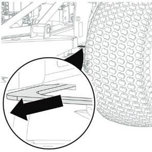
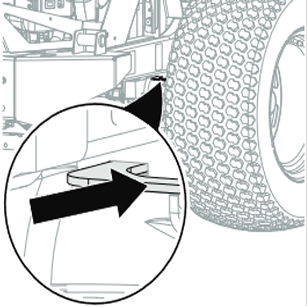
There is one transaxle bypass lever on each side of unit. Ensure that both levers are fully in front or rear position.
- Stop engine, remove key and wait for moving parts to stop and for hot parts to cool.
- Pull both transaxle bypass levers out into bypass position. See Figure 32.
- Remove brake actuator front pin and release brake.
- If on an incline, make sure any towing equipment and people are uphill to avoid any potential injury or collisions.
- Move unit to desired location.
- Reconnect brake actuator front pin and verify proper brake operation.
- Return transaxle bypass levers to operating position. See Figure 33.
NEVER secure unit to vehicle from rods or linkages that could be damaged.
Transport Unit
- With the engine off, push deck lift pedal completely forward to engage transport lock.
- Start engine and move unit to transport vehicle.
- Stop engine and remove key from ignition.
- Secure mower frame to transport vehicle.
Release Transport Lock
- With engine off, push deck lift pedal forward and lift transport lock release lever.
- Slowly return mower lift handle to resting position.
Adjust Seat
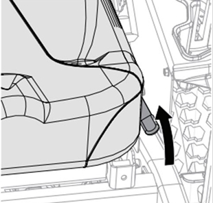
See Figure 34.
- Pull seat adjustment lever up to unlock seat.
- Move seat to desired position.
- Release seat adjustment lever to lock seat in place.
Lubricate Unit
- Apply oil to all pivot points and pin connections.
Lubricate Seat
- Place unit in service position. See Service Position.
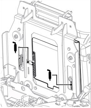
- Apply grease to seat tracks through slots under seat plate.
- Return seat to operating position and slide seat back and forth to spread grease along tracks. See Figure 35.
Check Mower Blades
Check blades for wear and damage. Replace or sharpen as needed.
AVOID INJURY. Use sturdy gloves or padding to protect hands when working with mower blades. Rotation of one blade rotates the other blades.
Unbalanced blades cause excessive vibration and eventual damage to unit. Balance blades before reinstalling on unit. NEVER weld or straighten blades.
Check Mower Belts
Check belts for wear and replace as needed.
Keep body parts away from idler when releasing idler spring tension.
Check Tire Pressure
- Place unit in service position. See Service Position.
- Check tire pressures. If needed, adjust to recommended pressures. See Tire Specifications below.
DO NOT exceed maximum tire pressure listed on tire sidewall.
Explosive separation of tire and rim parts is possible.
- DO NOT inflate tires above the recommended pressure.
- DO NOT inflate tires with a compressor; use a hand pump.
- DO NOT stand in front of tire assembly when inflating. Use a clip-on chuck and extension hose long enough to allow you to stand to one side.
Tire Specifications
| Specification | Value |
|---|---|
| Front Tire Size - in | 13 x 6.5-6 |
| Rear Tire Size - in | 22 x 10-12, 22 x 10.5-12, 22 x 11-12 |
| Recommended Front Tire Pressure - kPa (psi) | 137.9 - 172.4 (20 - 25) |
| Recommended Rear Tire Pressure - kPa (psi) | 82.7 - 103.4 (12 - 15) |
Check Battery
Battery posts, terminals and related accessories contain lead. Wash hands after handling.
Clean Battery
AVOID DAMAGE. DO NOT allow tools to contact metal surfaces when removing positive battery cable.
- Disconnect battery cables, negative cable first.
- Clean terminals and battery cable ends with a wire brush.
- Coat terminals with dielectric grease or petroleum jelly.
- Reinstall battery cables, positive first.
Always plug in battery tender when computer is on for more than 15 minutes, while engine is off.
Lidar Lens Cleaning
In normal conditions, the only maintenance required for the LiDAR sensor is to clean the optical window glass. Dust and stains on the optical window can negatively affect the performance of the LiDAR sensor. Make sure to regularly clean the optical window to prevent this from happening. First, check the surface of the optical window to see if cleaning is necessary. If it is necessary to clean, follow the steps below:
- Use compressed or canned air: DO NOT wipe a dusty optical window, as it will only cause more damage. Dust the optical window with compressed or canned air before wiping the optical window. If the optical window has no visible stains afterward, it is not necessary to wipe it also.
- Wipe the stains: DO NOT wipe using a dry lens tissue, as it will scratch the surface of the optical window. Use the lens tissue provided with isopropyl alcohol. Wipe slowly to remove the dirt instead of redistributing it on the surface of the optical window.
If the optical window is still dirty, a mild soap solution can be used to gently wash the window. Repeat Step 2 to remove any remaining soap residue.
Check Fasteners
Check for loose or missing hardware.
Check Parking Brake
- Place unit in service position.
- Bypass transaxles. See Move Unit Manually.
- Push unit forward.
- If unit does not move forward, no further action is needed.
- If unit easily moves forward, adjust the brake lever. Refer to your unit's Service Manual.
Check Engine Oil
Engine oil level must be maintained at correct level or engine damage may occur. Refer to engine manual.
Check Safety Interlock System
Check function of the Safety Interlock System by performing the tests below. Contact your RC Mowers dealer for repair if any of the tests fail.
Starting Interlock
| Test | Steering Levers | PTO | Parking Brake | Result |
|---|---|---|---|---|
| 1 | Neutral | Off | On | Engine starts. |
| 2 | Forward, Neutral, or Reverse | On | On or Off | Engine does not start. |
| 3 | Forward, Neutral, or Reverse | On or Off | Off | Engine does not start. |
Operating Interlock (Engine On)
| Test | Steering Levers | PTO | Parking Brake | Result |
|---|---|---|---|---|
| 4* | Forward, Neutral, or Reverse | On | On or Off | Engine shuts off. |
| 5* | Forward, Neutral, or Reverse | On or Off | Off | Engine shuts off. |
* When operator lifts off seat.
Check Hydraulic System
Check Hydraulic Oil Level
- Place unit in service position.
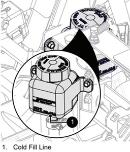
- Check oil level in expansion tanks. Oil should reach the cold fill indicator mark. See Figure 36.
Engine should be cold when checking initial oil level.
- Operate the engine for 1 minute and recheck oil levels.
- Add hydraulic oil, if needed.
- Remove expansion tank caps.
- Fill expansion tanks with 15W-50 Full-Synthetic Hydraulic Fluid until oil reaches the cold fill indicator mark.
- Reinstall expansion tank caps.
Change Hydraulic Oil and Filter
- Operate unit for a few minutes to warm hydraulic oil.
- Stop engine, remove key and wait for all moving parts to stop and for hot parts to cool.
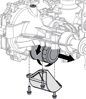
- Position container under oil filter to catch used oil. See Figure 37.
- Remove filter guard and oil filter from transaxle.
- Remove the vent / fill plug from the fill port and allow transaxle to drain completely.
- Wipe filter-mounting surface clean.
- Lubricate rubber gasket on new oil filter with clean hydraulic oil.
- Spin filter onto filter housing until it makes contact, and then turn filter 3/4 turn to tighten.
- Reinstall filter guard and torque to 7.3 N·m (65 lb.in). DO NOT overtighten.
- Add 15W-50 Full-Synthetic Hydraulic Fluid until oil appears at the bottom of the fill port (1892.7 mL (64 fl. ounces) per transaxle).
- Reinstall the vent / fill plug and torque to 20.3 N·m (180 lb.-in).
- Add hydraulic oil to expansion tank until oil reaches cold fill indicator mark.
- Repeat steps 3 - 12 for another transaxle.
- Purge hydraulic system.
Purge Hydraulic System
This adjustment requires operating the engine. Stay clear of moving parts and hot surfaces. Be sure unit is securely supported before starting engine. When engine is running, stand to the side of the mower - never directly in front or behind.
- Purge air from hydraulic system after draining oil or changing the filter.
- Park unit facing a wall or chock wheels.
- Release parking brake.
- Support unit so drive wheels are off the ground.
- Bypass transaxles. See Move Unit Manually.
- Start the engine and slowly move steering levers forward and backward 5 or 6 times.
- Return transaxle bypass levers to operating position. See Move Unit Manually.
- Slowly move steering levers forward and backward 5 or 6 times.
- Stop engine, lower unit to ground and check oil level. Add oil if needed.
- Repeat steps 1 - 8 until transaxles operate smoothly in forward and reverse at normal speed without excessive noise.
Electrical Service
Replace Fuse
To avoid damaging the circuit, replace fuses with fuses of the same amperage rating. Determine the cause of electrical failure and repair before replacing failed electrical components.
- Place unit in service position. See Service Position.
- Remove fuse box cover.
- Remove defective fuse.
- Determine cause of fuse failure and repair condition.
- Install new fuse.
- Replace fuse box cover. Ensure cover snaps tightly in position.
Replace Relay
Relays are interchangeable. Use only quality replacement parts.
- Place unit in service position. See Service Position.
- Remove fuse box cover.
- Remove defective relay.
- Determine cause of relay failure and repair condition. Install new relay.
- Replace fuse box cover. Ensure cover snaps tightly in position.